

Build the Graph
A Station is a graph of nodes connected through ports. This page shows how to add and name nodes, connect them, and keep a large graph tidy. You can change the graph on the Edit page and on the Live page; every change is saved automatically. The node types are explained in Key Concepts.
1. Add a Node
- Click Add node in the toolbar, or right-click the empty canvas.
-
Choose the node type: Gateway, Controller, Compound or Application.
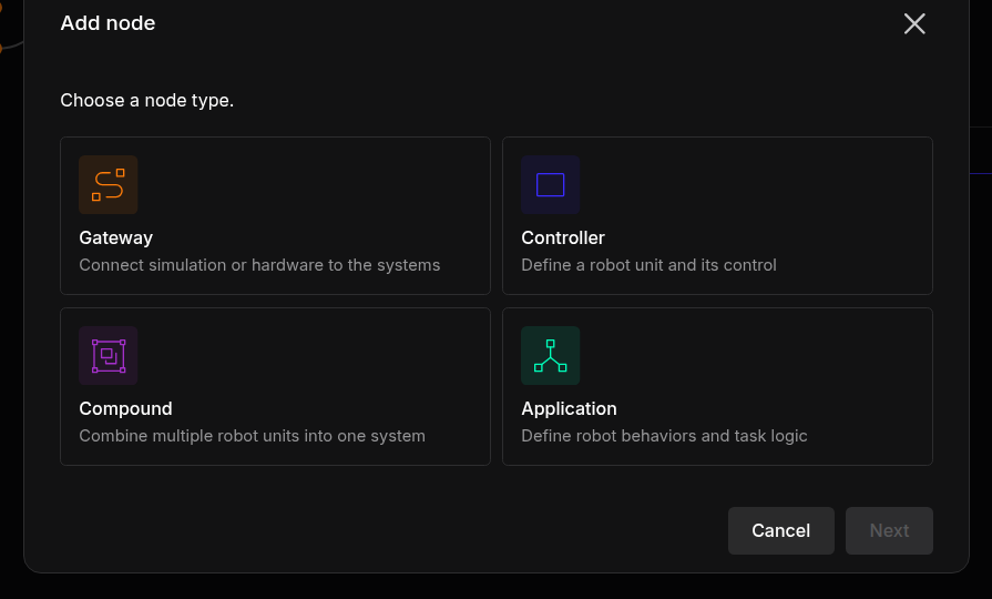
Choosing the node type -
Under Select a module, choose the app or module, then click Next.
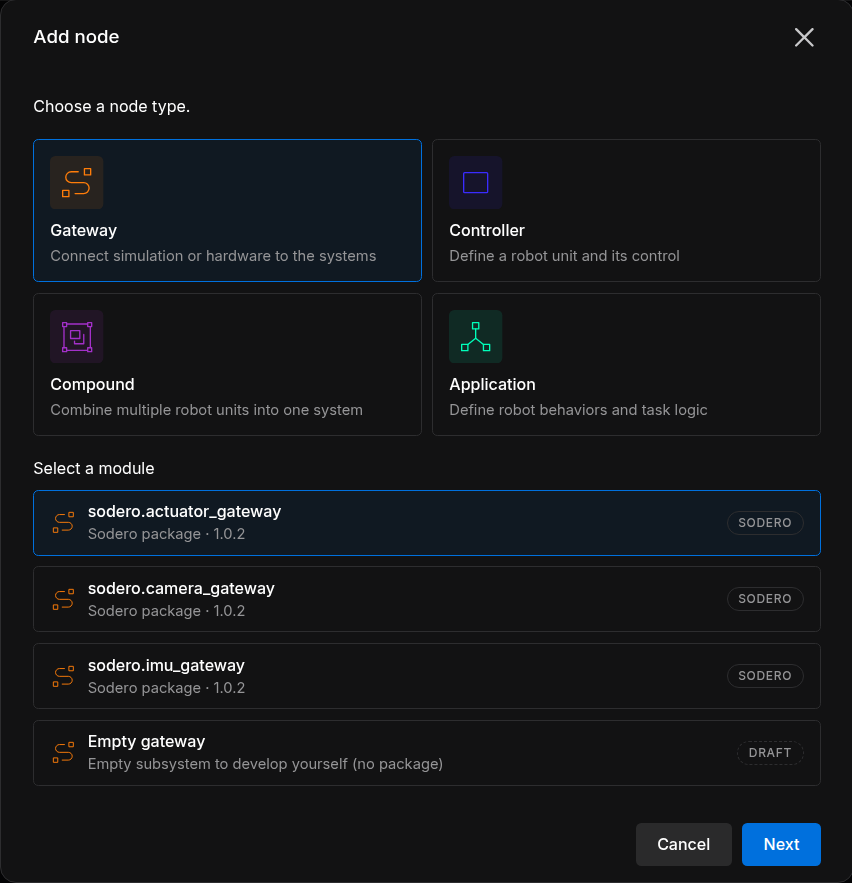
Gateway › sodero.actuator_gateway -
Enter the node name and click Add node. You can rename the node later.
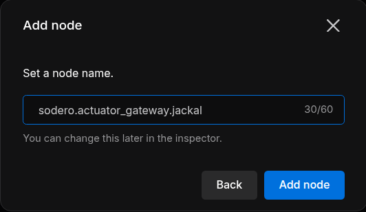
Naming the node
The node appears on the canvas as Planned. Nothing runs until you start it on the Live page (Start and Monitor Nodes).
The Module List
| Badge | Entry | Detail line |
|---|---|---|
| SODERO | An app installed from the Store | Sodero package · and its version |
| CUSTOM | A module package you uploaded | Imported package · Installed |
| DRAFT | Empty gateway, Empty controller, Empty compound, Empty application | Empty subsystem to develop yourself (no package): a placeholder with no program behind it, for sketching a system. It does not start. |
Each type lists only the apps and modules installed on this Station. To add another, install it first (Apps and Packages).
Name the Node
The name field proposes the app's own name, for example sodero.actuator_gateway. Add a last part that names the robot or device, so that the name reads sodero.<package>.<name>:
| Node | Example name |
|---|---|
| Actuator gateway of a robot | sodero.actuator_gateway.jackal |
| Mobile base controller of the same robot | sodero.mlc.jackal |
| Manipulator controller | sodero.mmc.arm |
| Articulation controller | sodero.amc.dog |
| Strider | sodero.strider |
- The last part names the node's documents. A new document you upload to
sodero.actuator_gateway.jackalis namedjackal(Documents and Settings). - Robot documents refer to their gateway by its node name, for example
sodero.actuator_gateway.jackal. Give the gateway the name its controller's document expects. - Give a robot's gateway and controller the same last part. The graph stays easy to read.
- Names use letters, digits,
_,.and-, start with a letter or digit, and have up to 60 characters (an empty draft: 20). Each name can be used once per Station: … is already a node of this graph: use another id, e.g. ….2.
2. Node Cards
| Part | Meaning |
|---|---|
| Title | The node name |
| Second line | The app or module the node runs |
| REQUIRES n/m | Ports the node needs from other nodes, on the left edge of the card: connected / total |
| PROVIDES n/m | Ports the node offers, on the right edge: ports with at least one connection / total |
| State | Planned until the node first starts, then its running state (Node States) |
The card border has the color of the node type: orange for gateways, blue-violet for controllers, purple for compounds and mint for applications. The arrow at the top right of a card folds its ports away.
3. Connect Ports
Connect a port that one node requires to a matching port that another node provides:
- Drag from one port dot to the other.
- Click one port, then the other.
- In the inspector of the node that requires the port, click Auto-connect next to the port. The Station connects the first matching port it finds, or shows No match.
The Station accepts a connection only when the two ports are on different nodes, one requires and the other provides, and both use the same interface. The inspector shows each port's interface under its name, for example api.actuator.servo.v1. The Station also keeps the system's structure:
- Only a controller may use a gateway.
- An application uses controllers or compounds, never gateways directly.
- One controller drives a gateway.
A refused connection says why, for example Connect ports on different nodes with opposite directions and matching contracts.
To remove a connection, select the node and click Disconnect next to the port in the inspector.
Check Auto-connect with several robots. Auto-connect does not look at node names: with two gateways in the graph, it may pick the other robot's. Check the result, or drag the connection yourself.
Common Connections
| Node (requires) | Port | Connect to (provides) |
|---|---|---|
sodero.mmc.<name>, sodero.mlc.<name>, sodero.amc.<name> |
servo_link |
The robot's actuator gateway sodero.actuator_gateway.<name>, port servo_link |
sodero.strider |
mobile_base |
The mobile base controller sodero.mlc.<name>, port mobile_base |
sodero.strider |
localization |
The localizer sodero.icp_localizer, port localization |
sodero.strider |
navigation |
The navigator sodero.navigator, port navigation |
sodero.icp_localizer |
camera (required) |
The robot's camera gateway sodero.camera_gateway.<name>, port camera |
sodero.navigator |
mobile_base |
The mobile base controller sodero.mlc.<name>, port mobile_base |
sodero.navigator |
localization |
The localizer sodero.icp_localizer, port localization |
Strider drives what its ports are connected to (Strider).
For navigation, install sodero.icp_localizer and sodero.navigator from the Store (Apps and Packages) and add them. The localizer needs its camera port connected; the navigator drives the base connected to its mobile_base port and follows the robot's position from the localizer connected to its localization port. Both read the Station's map bundle (Documents and Settings).
4. Rename and Delete
- Rename: click the pencil next to the node name in the inspector and enter the new name. The node keeps its connections and the documents it uses.
- Delete: right-click the node and choose Delete node. The dialog asks Delete "…" from this robot system?; click Delete node. The node's connections are removed too.
On the Live page, stop a node before you rename or delete it.
Deleting a node cannot be undone. Everyone working on the Station sees the change at once.
5. Find Your Way in a Large Graph
- Filter shows only nodes of one Node type or Status; Reset all clears it.
- Fit view zooms to show every node; Auto layout arranges the nodes by their connections.
- The N issues chip at the left of the toolbar lists problems, such as Required port "servo_link" is not connected. Locate jumps to the node.
6. Load and Export the Graph
- Export downloads the graph as a
.yamlfile. If something runs on the Live page that the graph does not show, it asks first: Planned topology only or Also include what is running. - Load YAML loads such a file from your PC (From your PC) or from the project library (Project Library). It replaces the nodes and connections of the Station (… loaded — N nodes now in the system.).
The file holds the graph only: nodes, their parameters and their connections. Documents, settings and apps are not part of it. To copy a whole Robot System, use Duplicate file, or Download local copy and Import, on the project page (Robot Systems and Robot Worlds).