

Articulated Robot (.sdda)
This tutorial builds the document of a robot whose joints are driven one by one, using a four-legged robot with twelve joints as the example. The document belongs to an Articulation node (sodero.amc.NAME). Unlike a manipulator or mobile base document, it describes no kinematics: only the joints, their limits and how the gateway's actuators drive them. How the controller uses the document is described in Articulation.
Before You Start
- On the Station, add a Controller › Articulation node, for example
quadruped, and an Actuator gateway for its motors (Nodes and Connections). - Connect the Articulation node's
servo_linkto the gateway. - Select the Articulation node and click Edit Stellar Designer.
A new Articulation node starts with one joint, joint_1. There are no templates; you add the joints of your robot one by one.
Step 1: Joint Configuration
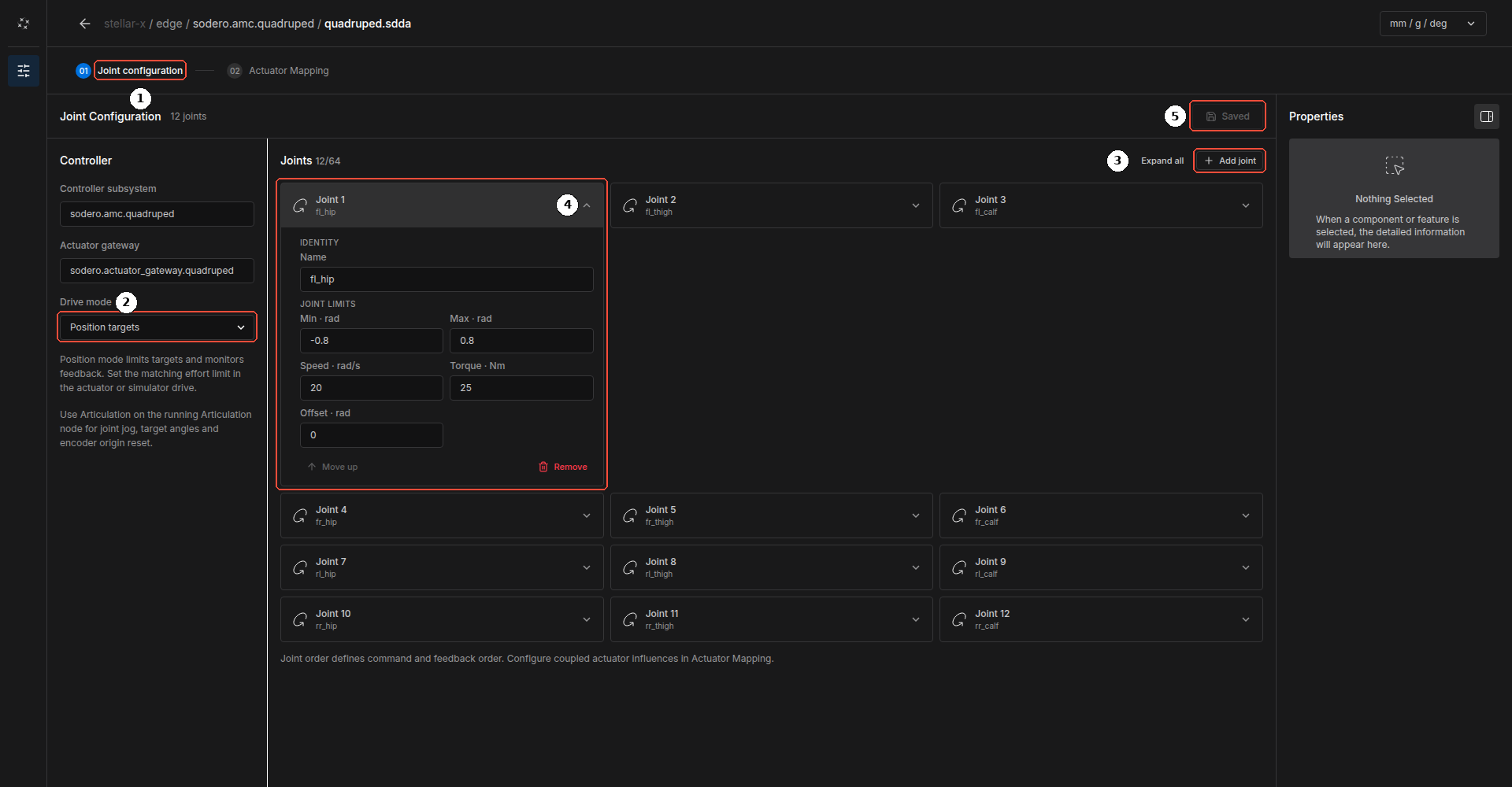
Step 01 Joint configuration ① shows the controller settings on the left and the joints on the right.
Controller:
| Field | Meaning |
|---|---|
| Controller subsystem | The ID of the node. The Station fills it in. |
| Actuator gateway | The gateway connected to the node's servo_link. The Station fills it in. |
| Drive mode ② | Position targets: the controller bounds the joint targets, and the drive (or the simulated joint) follows them with its own position control. Set a matching effort limit in the drive or the simulator. Bounded PD torque: the controller computes a torque from each joint's Kp and Kd and clamps it to the joint's torque limit. |
Joints: Add joint ③ adds a joint at the end of the list, up to 64 joints. Open a joint ④ to edit it:
| Field | Meaning |
|---|---|
| Name | A unique name of letters, digits and underscores |
| Min, Max (rad) | Range of motion. Targets outside it are refused. |
| Speed (rad/s) | Velocity limit, also the reference for the jog speed in Articulation |
| Torque (N·m) | Torque limit |
| Offset (rad) | Joint position at actuator position zero |
| Kp, Kd | Stiffness and damping, shown in Bounded PD torque mode |
Move up moves a joint one place up and Remove deletes it.
Each leg of the example robot (fl, fr, rl, rr) has a hip, a thigh and a calf joint, named for example fl_hip. The list runs leg by leg: fl_hip, fl_thigh, fl_calf, then the joints of fr, rl and rr. The example uses these values; enter those of your own robot:
| Hip | Thigh | Calf | |
|---|---|---|---|
| Min (rad) | −0.8 | −1.0 | −2.7 |
| Max (rad) | 0.8 | 3.0 | −0.9 |
| Speed (rad/s) | 20 | 20 | 20 |
| Torque (N·m) | 25 | 25 | 35 |
Joint order matters. Commands and feedback follow the order of the list. A program that sends joint targets must use the same order: Legged locomotion, for example, compares the joint names and their order with its walking policy and does not start if they differ (The controller joint order does not match the policy manifest.).
Save configuration ⑤ saves the document to the node; the button shows Saved when there is nothing left to save. Stellar Designer also saves when you return to the Station.
Step 2: Actuator Mapping
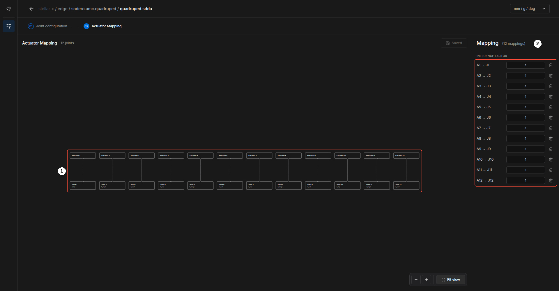
The canvas ① shows the gateway's actuators (top) and the joints (bottom); the right panel ② lists the INFLUENCE FACTOR of each connection. Every joint you add starts connected to the actuator with the same number, with factor 1.
Change the mapping as for a manipulator (Manipulator › Actuator Mapping): drag from an actuator's connector to a joint's connector, set the influence factor, and use a negative factor to reverse a direction. Several connections describe coupled joints. The mapping uses as many actuators as there are joints, and it must be invertible: every set of joint targets must correspond to exactly one set of actuator commands.
Actuator n here is actuator n of the gateway. The gateway must provide at least as many actuators as the document has joints.
Save a Copy
To save the document to your computer, click the Stellar mark at the top left and choose Definition › Download .sdda. You can import the file into another Articulation node with Import .sdda (Design Documents).
Try the Robot
Real hardware moves. Support a legged robot so that its feet are off the ground, keep the area clear and keep the emergency stop within reach.
Start the gateway, then the Articulation node, and click Articulation in the node's CONTROL section (Articulation). Switch the servo on and jog each joint at a low speed. Check that:
- each joint moves in the expected direction,
- each joint stops at its limits,
- the joint monitor shows the expected angles in a known pose. Correct a joint's zero with Offset, or with Set origin in Articulation.
This guide ends with this manual joint test. A program that sends joint targets, such as Legged locomotion with a walking policy, needs its own preparation, which this documentation does not cover: its joint names and order must match the document (Step 1), and it must be tested with the robot supported off the ground.