

Stellar Designer
Stellar Designer creates and edits the design documents of gateways and controllers: the robot's structure, its limits and safety settings, and how the gateway's actuators drive its joints or wheels. Each actuator gateway and controller node on the Station holds one document:
| Document | Describes | Node | Page |
|---|---|---|---|
.gw |
The actuators and the hardware that drives them (EtherCAT drives or Isaac Sim) | Actuator gateway | Gateway Designer (.gw) |
.sdd |
Manipulator (serial arm) | Motion Studio | Manipulator (.sdd) |
.sddm |
Wheeled mobile base | Strider | Mobile Robot (.sddm) |
.sdda |
Articulated robot driven joint by joint (legged robots, humanoids) | Articulation | Articulated Robot (.sdda) |
A 3D model (.glb) for display is optional (3D Model Creation). This page covers the controller documents. Gateway documents (.gw) are edited in the Gateway Designer, the part of Stellar Designer for .gw files, described with the gateways.
1. Open Stellar Designer
- On the Station, select a controller node (Motion Studio, Strider or Articulation).
- Click Edit Stellar Designer in the node's DEFINITION section.
Stellar Designer opens in a new tab with the node's document. Changes are saved back to the node automatically; in an Articulation document, click Save configuration. Stop the node before you edit its document; the new document takes effect the next time the node starts.
If a Motion Studio or Strider node has no document yet, Stellar Designer opens Create robot definition: choose a template of the robot type, or Blank robot for a manipulator, click Next, then Create. An Articulation node starts with a document of one joint.
| Robot type | Templates |
|---|---|
| Manipulator | 2-axis two-bar arm, 4-axis SCARA, 4-axis cylindrical SCARA, 7-axis humanoid arm, Blank robot |
| Mobile | Differential drive 2WD, MiR250 differential, Skid steer 4WD, Mecanum 4WD, Swerve 4WD, Ackermann |
You can also import a document you already have with Import in the node's DEFINITION section (Design Documents).
2. Screen Layout
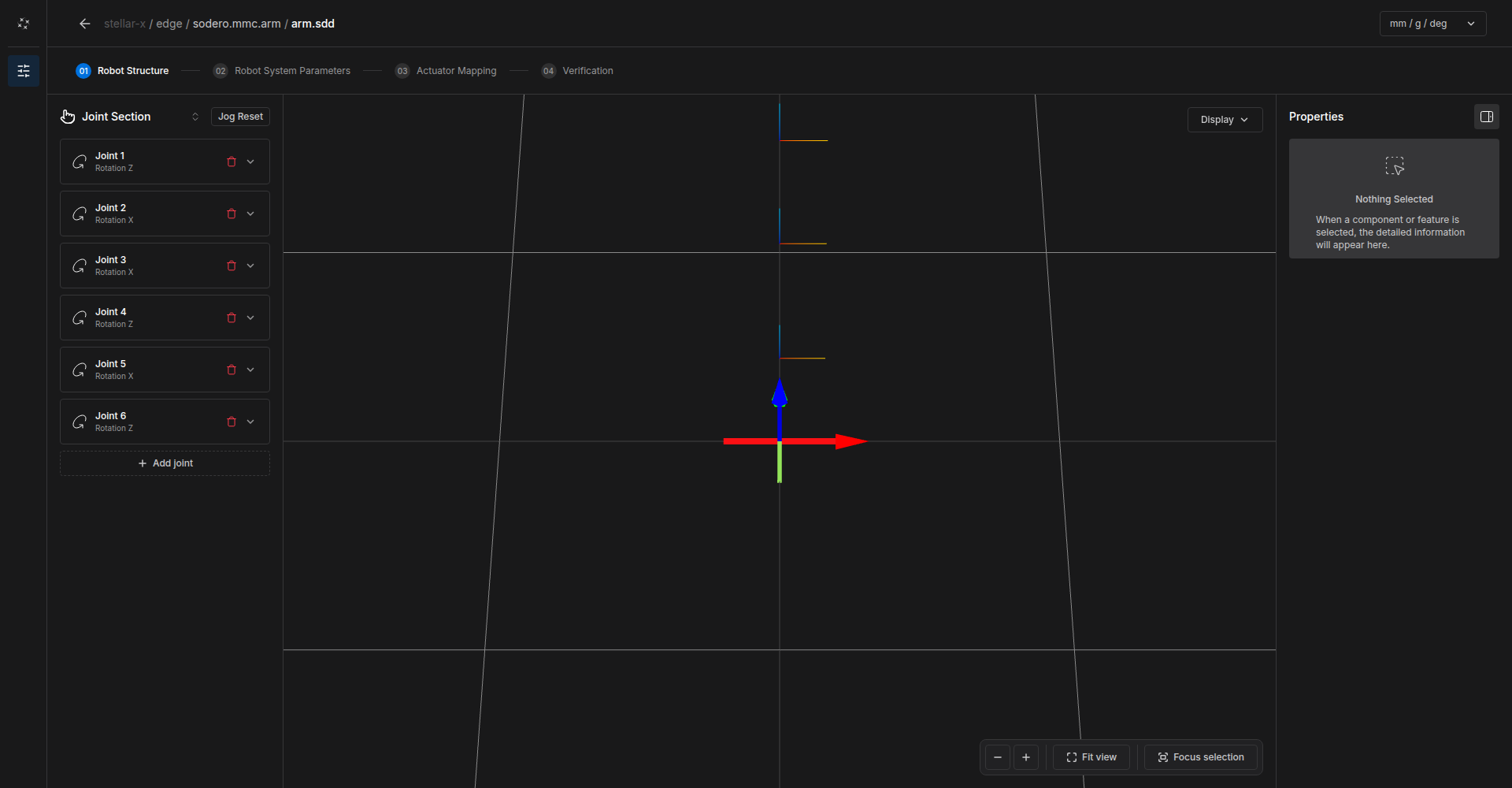
| Area | Description |
|---|---|
| Breadcrumb | Where the document belongs: device / Station / node / file. The arrow returns to the Station. |
| Steps | 01 Robot Structure (or Chassis Structure for mobile robots), 02 Robot System Parameters, 03 Actuator Mapping, 04 Verification. An Articulation document has two steps: 01 Joint configuration and 02 Actuator Mapping. Click a step to open it; you can go back and forth. |
| Left panel | The joints (or wheels) of the robot, with their parameters |
| 3D view | The robot as you define it. Drag to rotate, right-drag to pan, scroll to zoom. Fit view frames the robot; Focus selection frames the selected part. |
| Right panel | Details of the selection, such as constraints, or the parameters of the current step |
| Units | mm / g / deg or m / kg / radian. Display only; documents store SI units. |
Display Menu
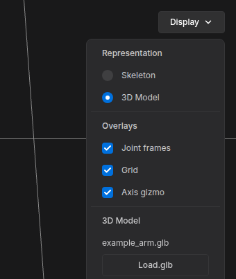
Display in the 3D view switches between Skeleton (joint frames and links as lines) and 3D Model, and shows or hides Joint frames, Grid and Axis gizmo. Load.glb attaches the robot's 3D model, a GLB file, to the document; Motion Studio then shows the robot with it (3D Model Creation).
3. Workflow
- Structure. Define the joints (manipulator) or the chassis and wheels (mobile robot).
- System parameters. Enter the robot-wide values: payload, gravity, speed limits, goal tolerances, safety margins.
- Actuator mapping. Connect the gateway's actuators to the joints or wheels, with their transmission factors.
- Verification. Click Verify. When all checks pass, the document is ready; Export saves a copy to your computer.
An Articulation document has only the joints with their limits and the actuator mapping (Articulated Robot).
Then start the node on the Station and try the robot, in simulation first.